Step 5: Install CPU Probe or Serial Cable
Good news! [machine_type_short] does not require a CPU probe, so you can skip to the next section.
Scorbit does not requite a CPU Probe for Stern SAM machines. However, it does require a special RS-232 ribbon cable to be installed alongside the DMD Probe. Also, Stern SAM games require a special patch made to the game ROM made in the final activation step.
Locate the DB9 Connector
Find the location of the DB9 connector on the Stern SAM MPU board. It is located just below the DMD connector.

Insert Stern SAM Cable
Insert the provided DB9 (9 pin) RS-232 ribbon cable into the male DB9 connector.


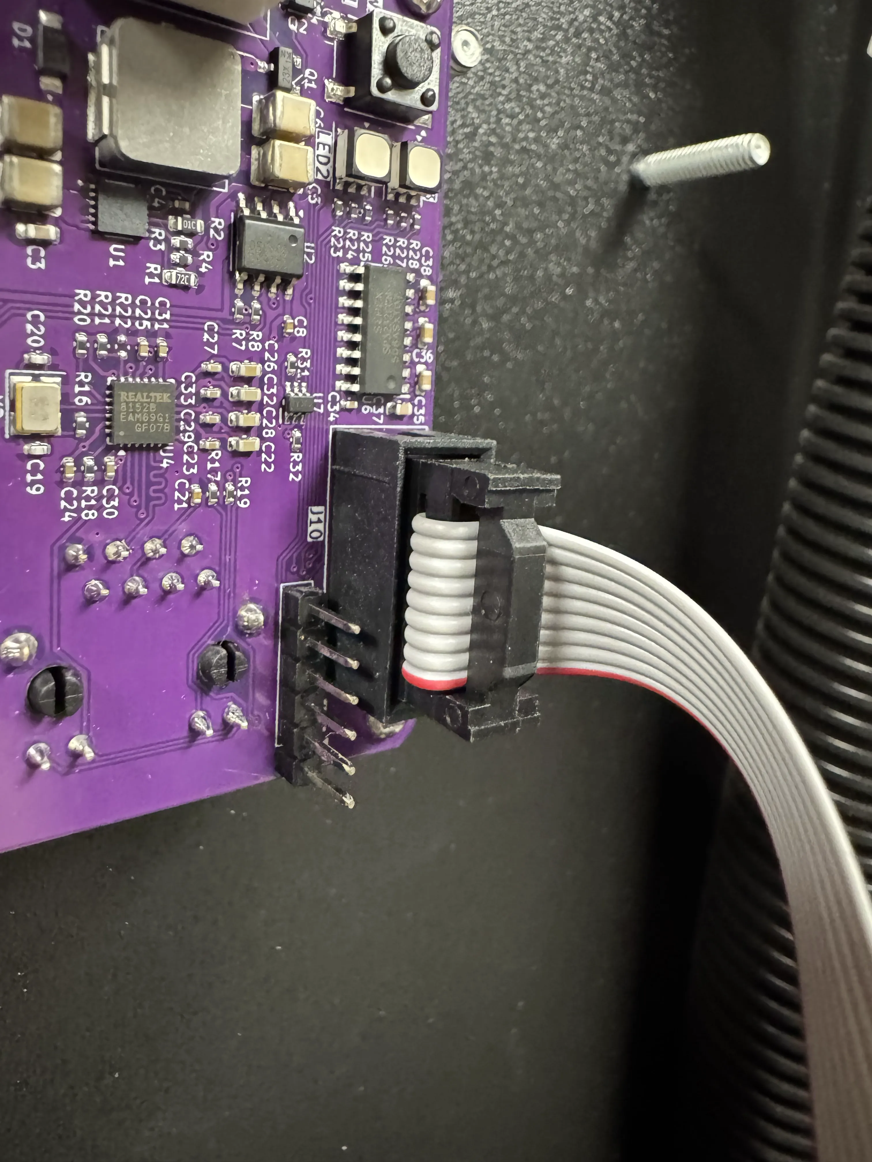
Connect the SAM Cable to the Scorbitron
Insert the other end of the DB9 cable into the black 10 pin IDC connector on the Scorbitron. The connector is keyed and should only fit in one orientation.
The Scorbit CPU Probe is an interloper board for your [machine_type_short]. This means that it sits between the game's CPU chip and the game's MPU board. The design of the CPU Probe does not require power for the CPU to function normally. However, when connected to the Scorbitron, the combo is quite powerful, allowing you to read and write data directly to and from the game, change settings, and even add credit or start games.
Note regarding installation of the CPU Probe
The machine CPU is one of the most important components of the machine. It is fragile and should be handled carefully. Particularly with older CPU chips, replacing them may be challenging if you are not experienced. This being said, with a small amount of preparation, it is a safe and quick operation. We strongly recommend that you use a chip extraction tool to avoid bending pins. Please watch the accompanying video for some tips and tricks to making this process as smooth as possible.
CPU PROBE PINS ARE FRAGILE!
Keep the included anti-static foam on the rear pins of the CPU Probe at all times during this step, as they are very fragile. Only remove the protective foam when you are ready to insert the probe into the MPU socket at the end of this installation step.
Locate the CPU
Gottlieb 6502
Your [machine_type_short] uses a 6502 processor. In most cases with original equipment, the CPU is soldered to the MPU board. In order to use the Scorbit CPU Probe you either have to be using a modified MPU board that has been socketed, an aftermarket board that uses a socket, or the Scorbit A2 Adapter (not yet available). Please ensure you have one of these options before you proceed.
Power down your machine before proceeding. Open the backbox of your [machine_type] and locate the CPU. This is an example of a [machine_type_short] CPU:
Note the orientation of the notch on the CPU chip as it relates to the socket on the MPU. It is always useful to take a photo of the chip in its original orientation. Some games have more than one CPU chip of the same type, be sure to find the exact one in the photo.
Early Bally and Stern Alltek and Barkandl/NVRAM (aka Weebly) Retrofit Boards
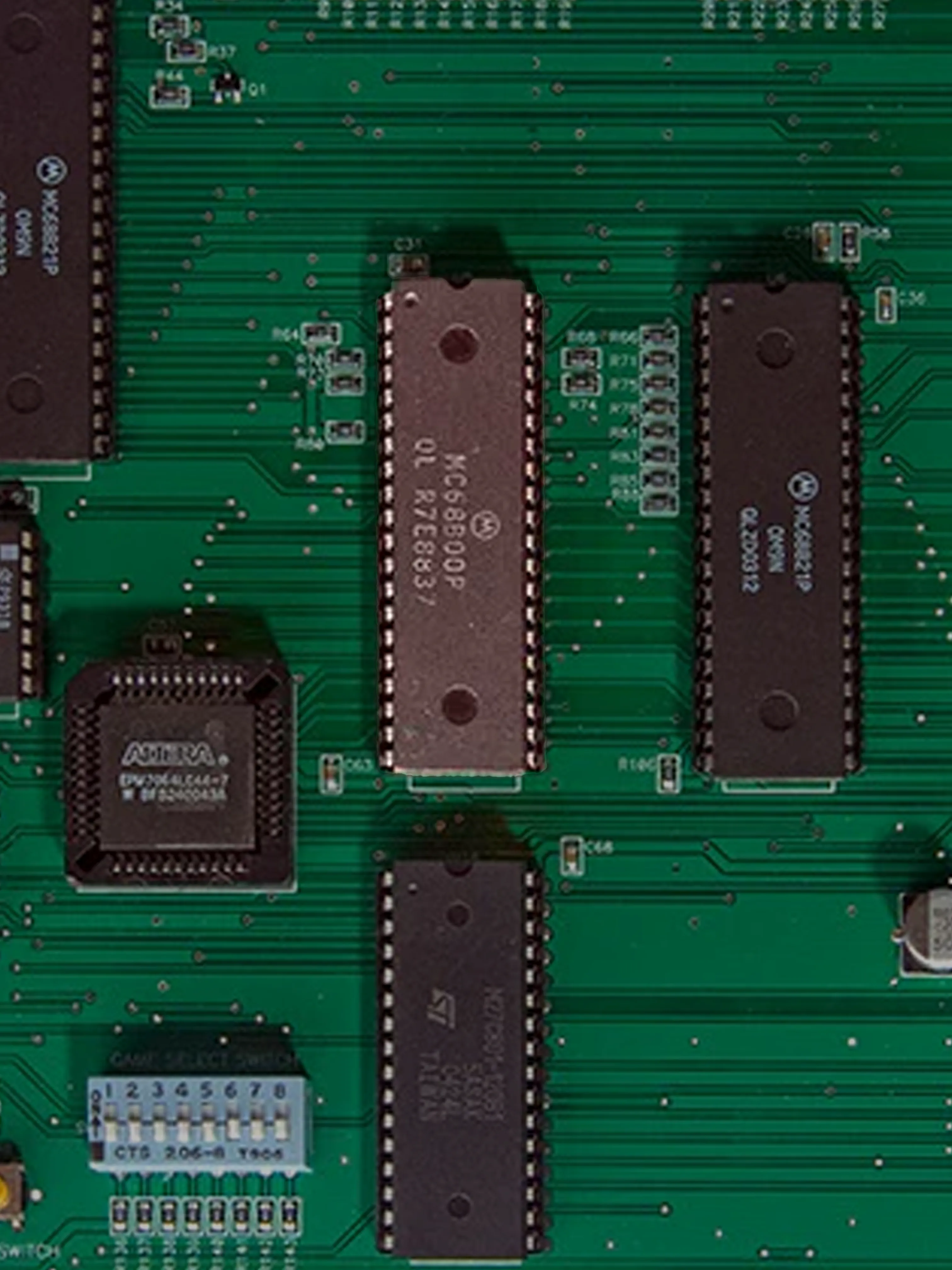
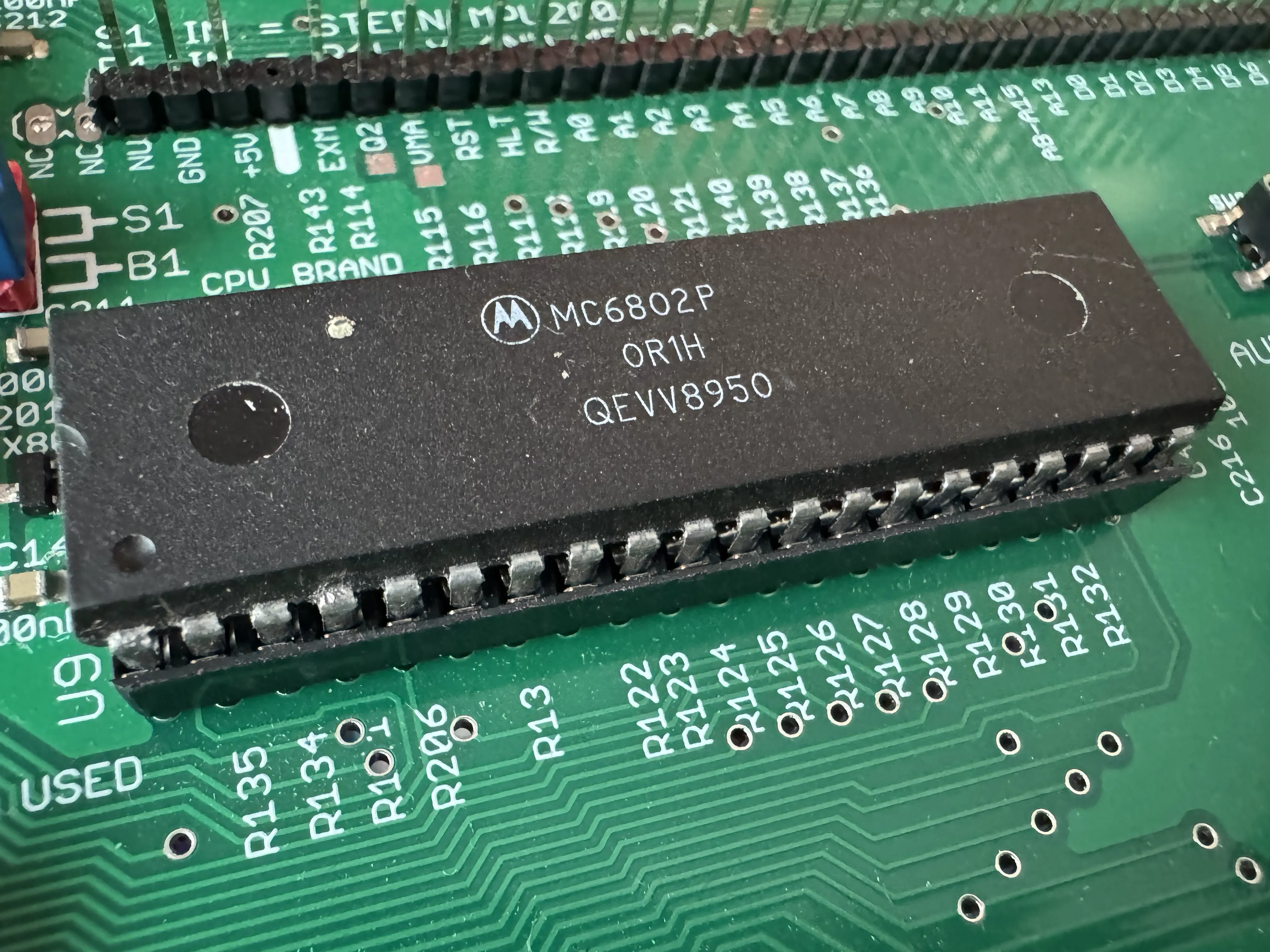
In many cases, your machine may be using an after-market retrofit replacement board, such as the Alltek Ultimate MPU or the Barakandl (NVRAM/Weebly). It is important to know if this board is original or retrofit, as the locations of the CPU chip may be different. Also, the Weebly board uses a 6802 instead of a 6800 processor, which requires different jumper settings on the CPU Probe. Inspect your board, and if it's not old, it's probably one of these. Note this for later in the installation. On the Alltek, the 6800 CPU is labeled U5. On the Weebly, the 6802 CPU is labeled U9.
Remove the CPU
If the MPU board is in an awkward position to perform the extraction, we recommend removing the MPU board from the game to perform this step. If you are experienced and have the reach and access to the MPU, you may remove the CPU without removing the MPU board. Just remember not to rush this and do not remove any component that is soldered to the board.
Using a CPU extraction tool or soft CPU prying tool, gently remove the CPU chip from the socket on the MPU board. Take your time, and be careful not to bend any pins.
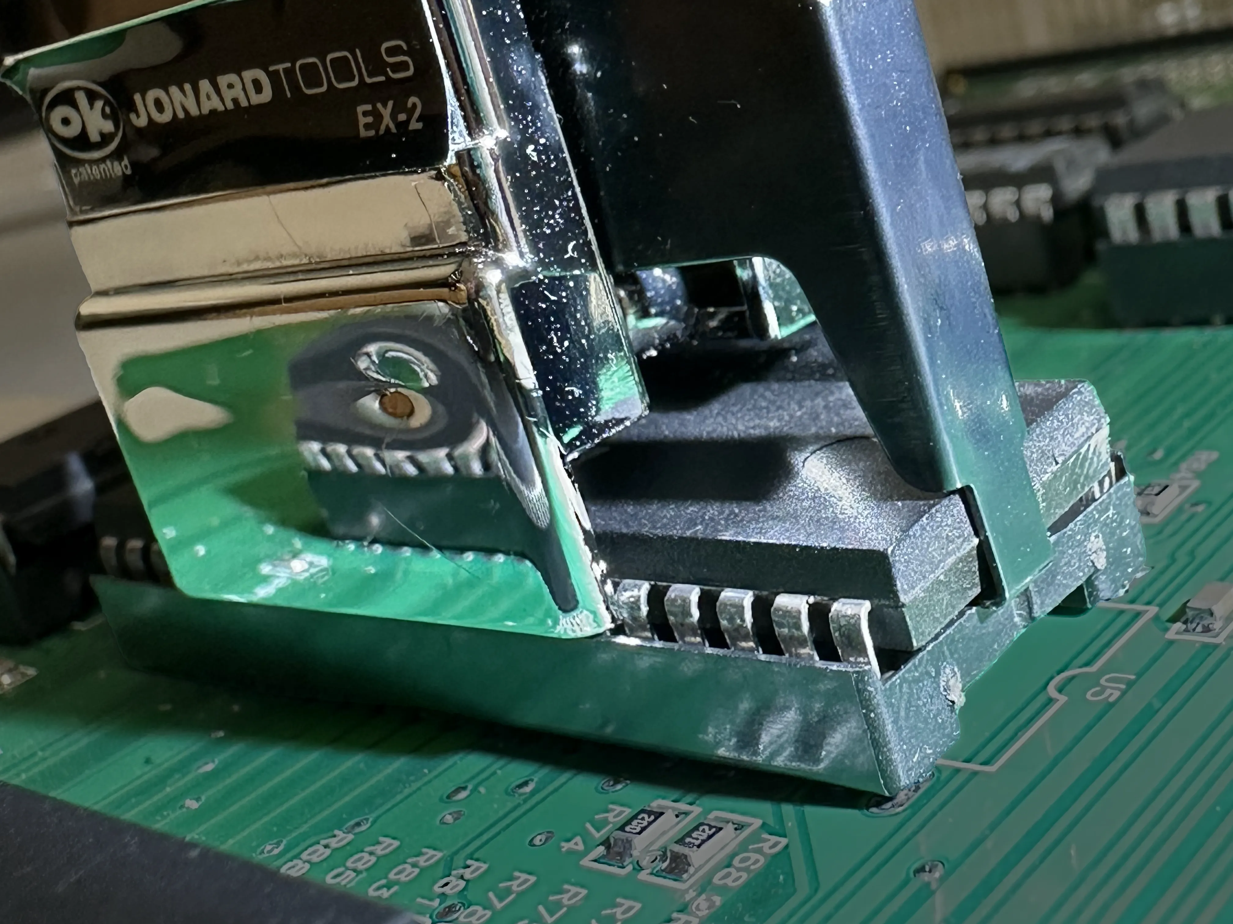
If you are using the prying method, we recommend alternating from the flat sides of the chip (notch side and opposite side), placing the pry tool underneath each side of the chip and prying in tiny, small amounts. Do not to place any pry tool underneath the underlying socket, only between the chip and the socket, because you do not want to pry off the socket! Once the chip has come off the board enough, you can slide your pry tool under the whole chip, and rotate the tool to move the chip off the socket.
Set the chip aside on some anti-static foam, paying close attention to the location of the notch and inspect and correct any bent pins. Also inspect the original (now empty) socket on the MPU. This is a great time to clean the contacts. You can also use this time to determine if there is enough room between the socket and the MPU board to slide in a cable tie to secure the CPU probe later. There is often an air gap between the socket and the PCB, and usually you can carefully insert a cable tie through the gap.

Configure the CPU Probe for Your Machine
CPU PROBE PINS ARE FRAGILE!
Keep the included anti-static foam on the rear pins of the CPU Probe at all times during this step, as they are very fragile. Only remove the protective foam when you are ready to insert the probe into the MPU socket at the end of this installation step.
First become familiar with the Scorbit CPU Probe and note the orientation of the original CPU chip and the notch on the chip.
Remember to keep the original anti-static foam over the pins of the CPU probe to prevent any damage until you are ready to insert it into the MPU board.
In preparation, the CPU Probe must be configured for the CPU used by the MPU. The CPUs installed on most MPUs generally are the same for all machines for the same type, with some minor exceptions such as retrofit boards. You'll find three 18 pin connectors on the edge of the CPU probe.
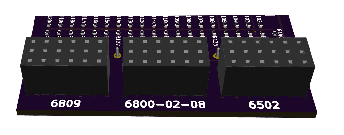
Each of these "bridge connectors" are designed to fit over the jumper pins S1-S6 for different CPU types.
- 6809/6809E on the left labeled "6809."
- 6800, 6802, 6808 in the middle leabeled "6800-02-08."
- 6502 on the right labeled "6502."
Break off these keys from the CPU probe board. Slide the key over the jumper pins as shown.
Barakandl NVRAM/Weebly Retrofit Boards
If you are using the Barakandl NVRAM/Weebly retrofit board, the jumper settings should be set for 6802, not 6800.
Align CPU chip over Scorbit CPU Probe Socket
CPU PROBE PINS ARE FRAGILE!
Keep the included anti-static foam on the rear pins of the CPU Probe at all times during this step, as they are very fragile. Only remove the protective foam when you are ready to insert the probe into the MPU socket at the end of this installation step.
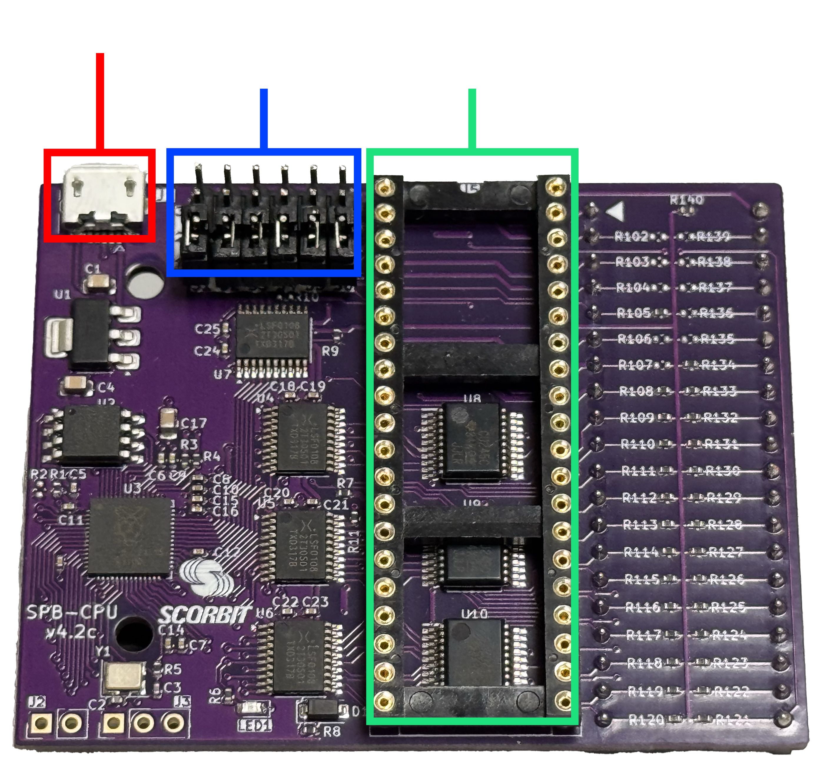
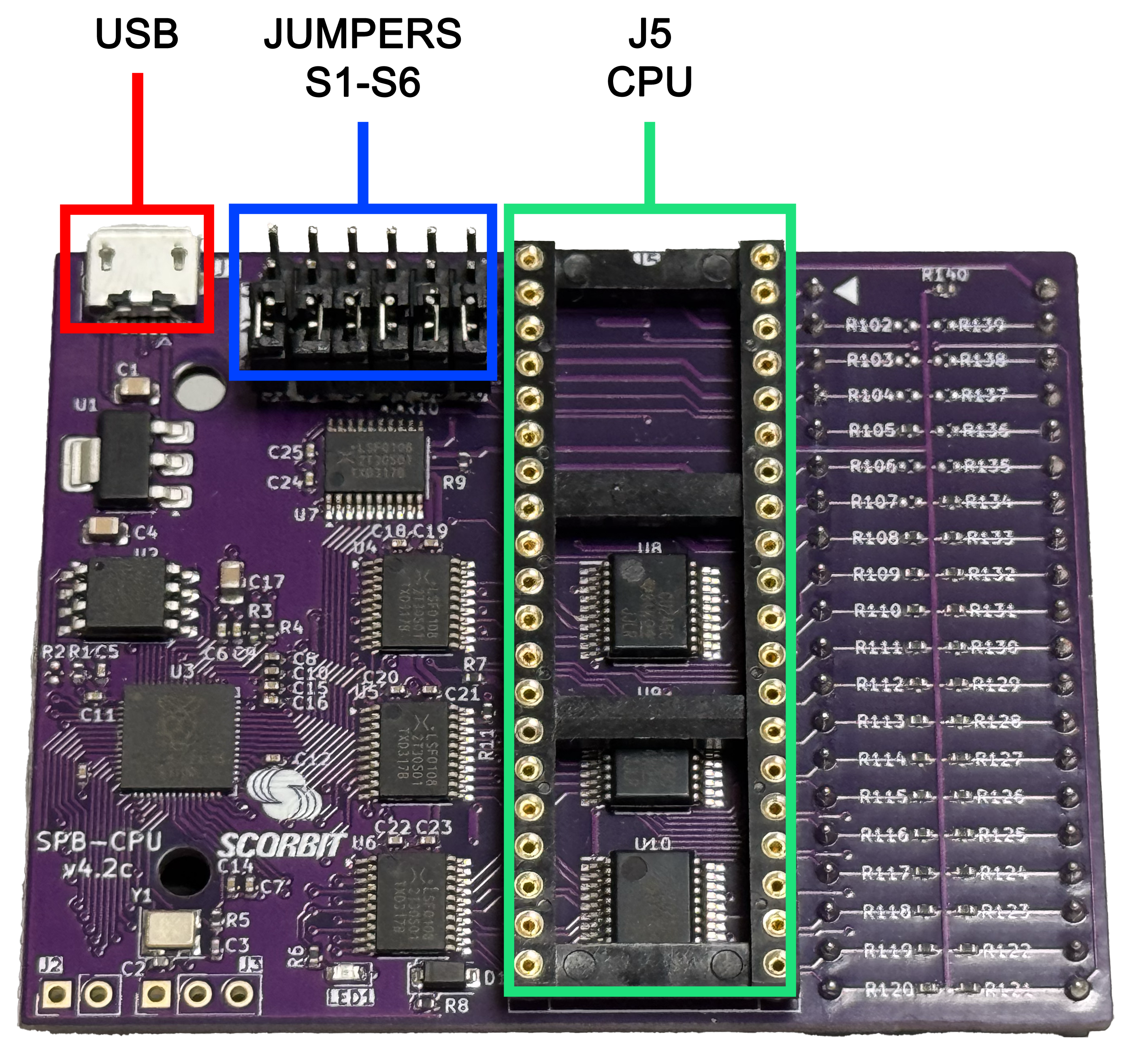
Locate the J5 CPU socket on the Scorbit CPU Probe. You will see that it looks similar to the socket on the MPU. Also identify the notch on one side of the socket, with an illustration silkscreened on the PCB.
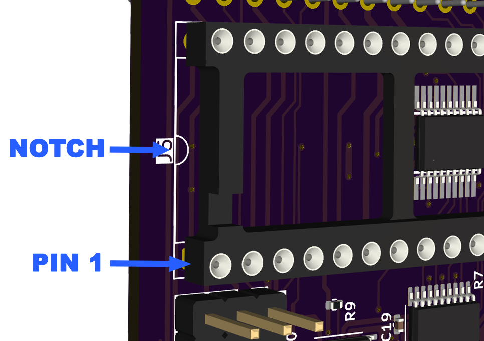
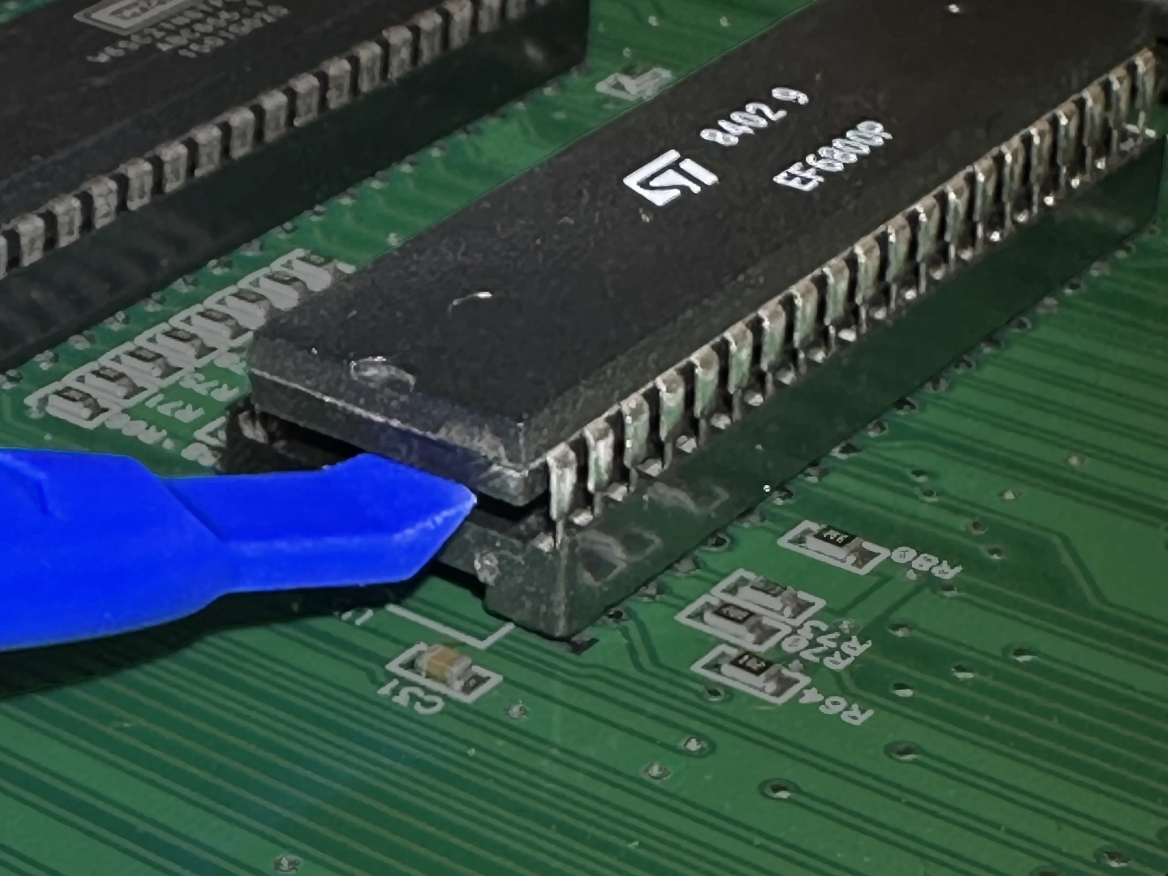
Place the CPU chip over the socket on the Scorbit CPU Probe, aligning the notch with the notch label silkscreened on the side of the probe's CPU socket. We recommend placing one row of pins precisely over a row and slightly into the socket first, so that one row is slightly outside the socket.
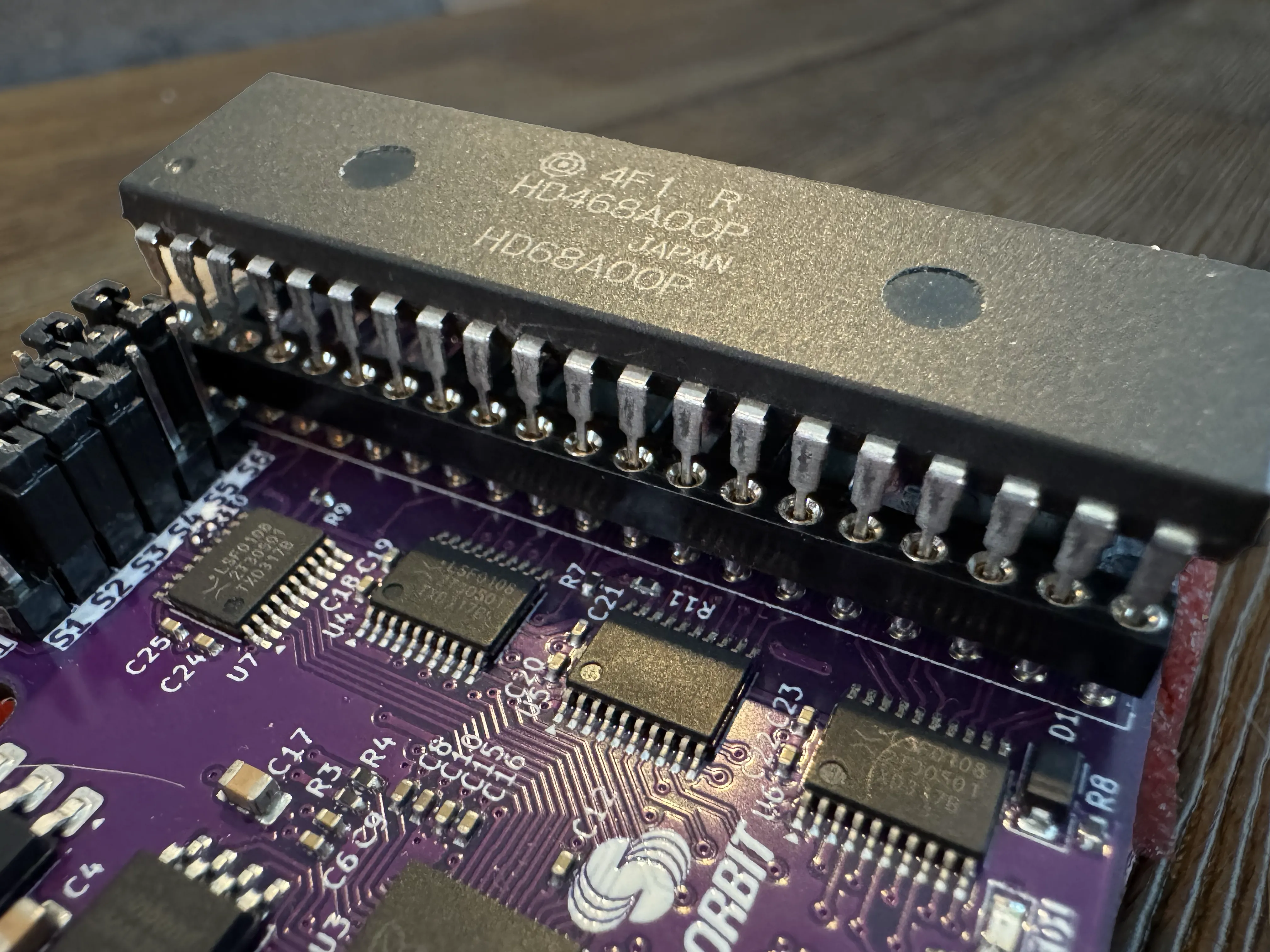
While placing one finger over the top of the chip, using a flat tool such as a pry tool or popsicle stick, gently run the tool against the pins that are outside the socket, so they all are slightly bending into the socket at once. When all the pins are all in the holes, the chip should gently fall into the holes on both sides. Take your time, and if the other row of pins pops out, start over.
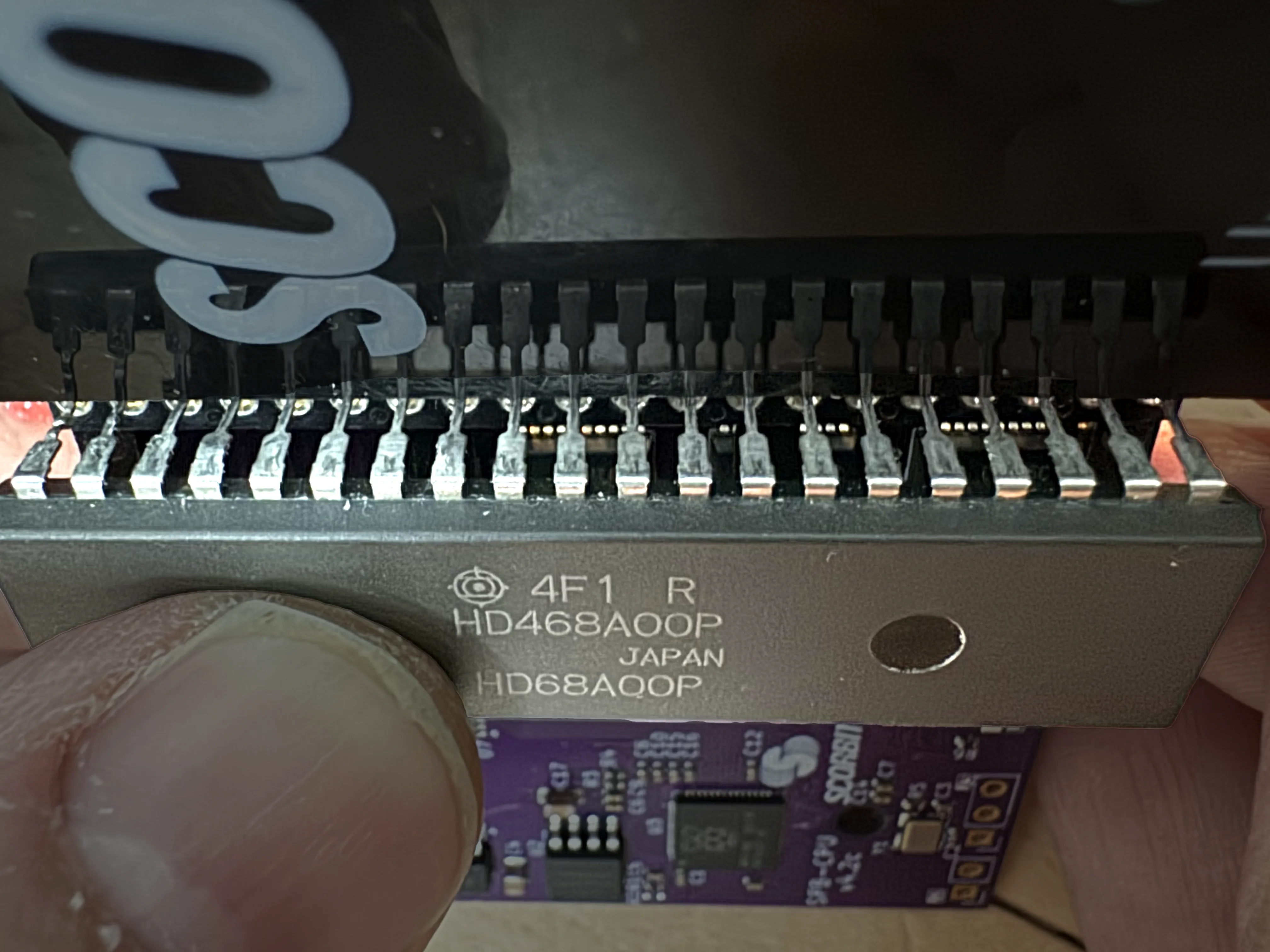
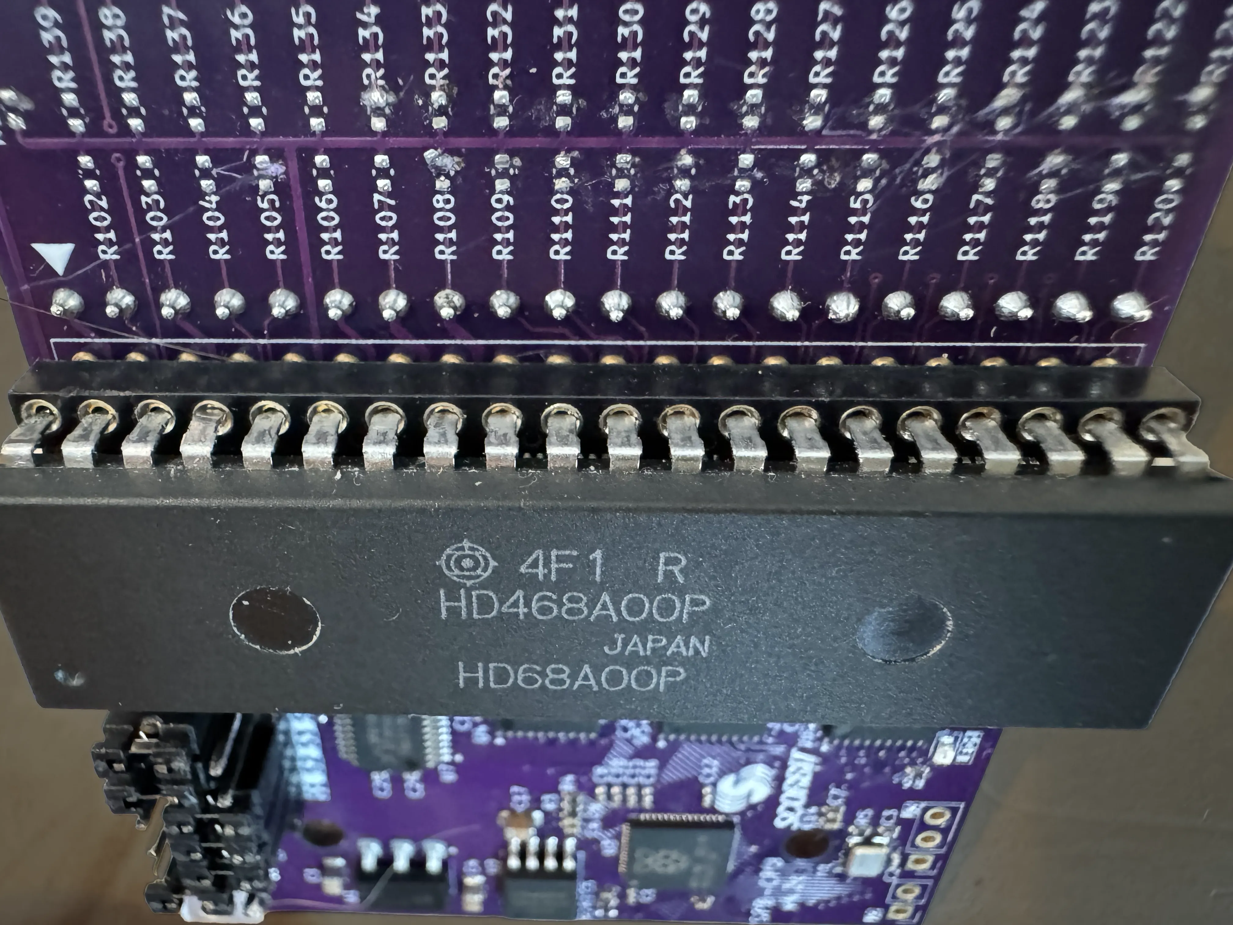
Reinspect All Pins and Insert Chip
Renspect each of the CPU pins as they enter the socket holes to make sure everything is aligned, then use slight pressure on the top of the chip to insert the chip into the socket. You can run your finger back and forth across the top until it falls further into the socket, then finally apply more pressure until the chip snaps into place.
Attach A1 Adapter
Your [machine_type_short] machine requires the A1 adapter, which allows the CPU Probe to be installed 180 degrees on the MPU board. Using the supplied A1 adapter, gently connect the CPU Probe and the A1 adapter together, using the provided standoffs. The pins should go in the socket while the standoffs go into the holes of the CPU Probe. Make sure the pins are in place, then apply significant pressure to both boards until the spacers snap through the holes. Beware not to apply pressure to any of the pins or components, as they can break off under direct pressure.
Image: attach-a1-adapter.gif
Optional: Prepare the MPU board for the CPU Probe
We have found that older machines, particularly from the 80's and earlier, often have a certain amount of elasticity in the existing socket. Sometimes this is caused by oxidation or aging with the metal in the socket.
To preserve the machine and protect against repeated insertions into the existing MPU socket, we recommend placing the provided additional socket into the existing socket, essentially layering two sockets. This allows you to use more force to press in the new socket as you apply pressure without pushing hard on the actual CPU or CPU Probe.

If the original socket feels elastic and not gripping the additional socket, we recommend using the single-row sockets that we have included with the CPU Probe. These single-row sockets may require significant pressure to get them fully inserted, and in rare cases requires removal of the MPU board to a flat surface before proceeding. In those cases, single-row sockets often provide better staying power because they can be independently pressed into each row at varying levels of force. Once these sockets are in place, it becomes a cleaner, better contact connection for the CPU Probe with less wear and tear to the original socket.

Now is also a good time to inspect the MPU board and how the original socket is layered onto the board. If there is any space between the socket and the circuit board, we recommend putting a thin cable tie behind the original socket that can be wrapped around the CPU probe when inserted, to prevent the assembly from falling out when the machine is moved.

Install the Scorbit CPU Probe and Attach USB Cable
Attach the CPU Probe to the socket on the MPU board. It should click into place. If you find the socket pushes the probe out, be sure to complete the previous step. If the MPU board accommodates it, use a cable tie to hold the CPU probe to the MPU board. Connect a short micro USB cable to the probe and the other end to one of the micro USB ports on the purple Scorbitron board.
If you chose to fasten the CPU Probe to the MPU using a cable tie, make sure to avoid tightening the cable tie such that it pulls the socket away from the MPU. The cable tie is meant to relieve strain and keep the CPU Probe from falling forward.

At this point, you can confirm the installation was done properly by powering up the game and ensuring that it boots, even with the Scorbitron powered down. If there are any issues, power down, carefully inspect the alignment of the pins, and ensure the chip and probe are firmly seated completely in the MPU socket. If the probe has any looseness or "play," or seems to too easily fall out of the socket, consider using the single-row CPU socket pins mentioned above between the socket and the probe or using a cable tie to wrap around the probe and the socket together, pulled tightly so the probe remains attached.
Troubleshooting When Game Does Not Boot
At mentioned, if you power up your game at this stage, the game should boot normally. If the game does not boot, these are some of the potential reasons that may cause an issue:
- The jumper pins at S1-S6 are not set properly. Ensure the jumper key is aligned correctly, not offset and not 180 degrees. You can use the guide on the back of the probe if you would prefer to use individual jumpers.
- The CPU probe or underlying sockets are not fully seated in the game MPU. Often you can test this by applying slight pressure as you power up the game.
- The CPU probe is "offset" to the left or right on the CPU socket, and pins are not precisely aligned.
- The CPU chip in the probe is upside down from the original orientation. Compare the notches.
- A pin on the CPU chip is bent and not fully inserted into the CPU Probe. Carefully remove the CPU Probe and closely inspect each pin on the chip individually. If you have a bent pin, carefully remove the CPU chip using an extraction tool and slowly, carefully flatten the pin back into its original shape. Do not bend the pin repeatedly or it will snap off. Once you have the pin back in place, repeat the process above to re-insert the CPU chip into the CPU probe, aligning the notches.
- If used, the A1 adapter is not properly connected to the CPU Probe. Inspect how the adapter is attached to the CPU Probe and sure there are no broken or bent pins.
- The entire probe assembly is installed upside down. The way to confirm this is to match the notch on the MPU to the notch on the CPU socket and the notch on CPU chip on the probe, unless the A1 adapter is used.