Step 6: Install Scorbit Tap Pad
Run Tap Pad USB Cable
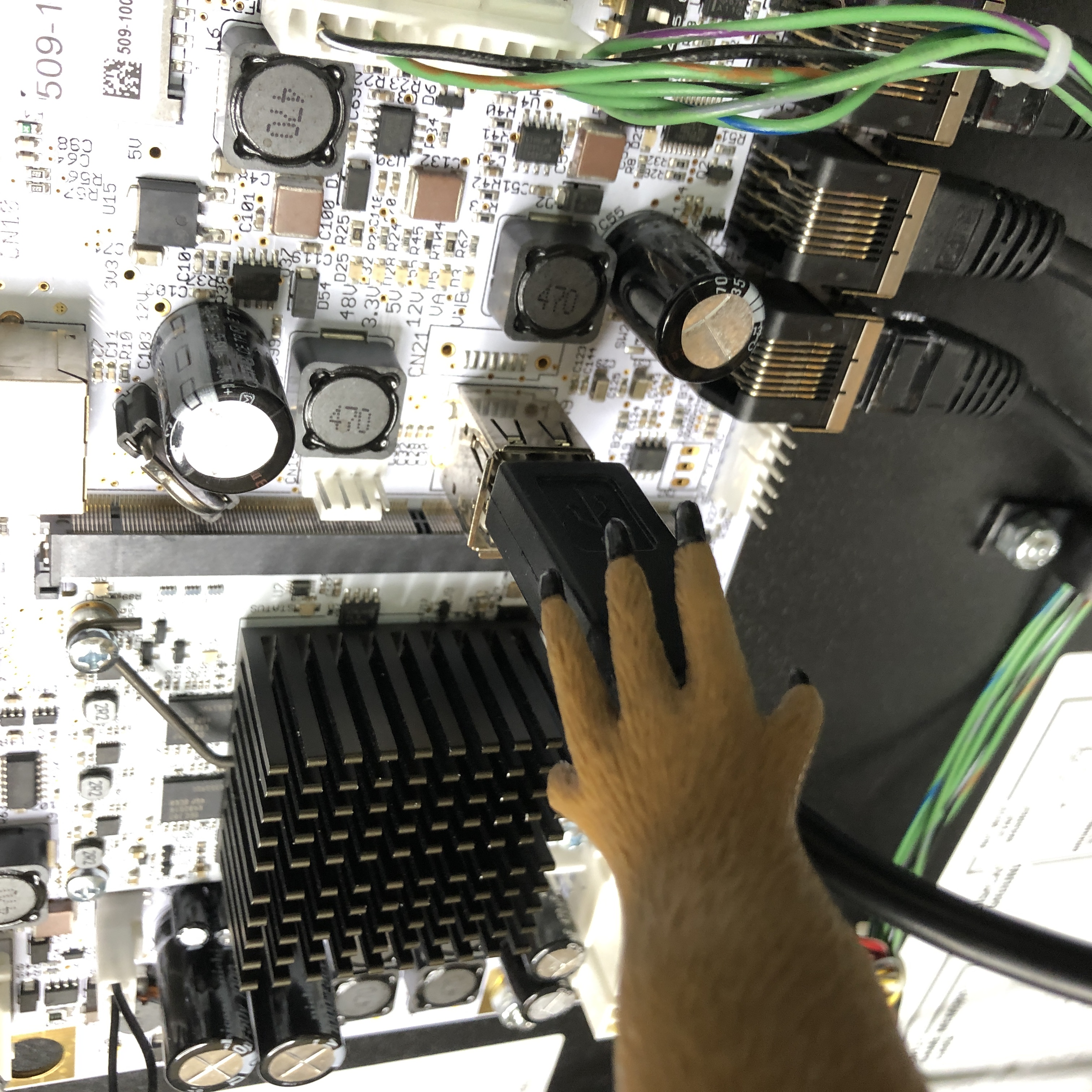
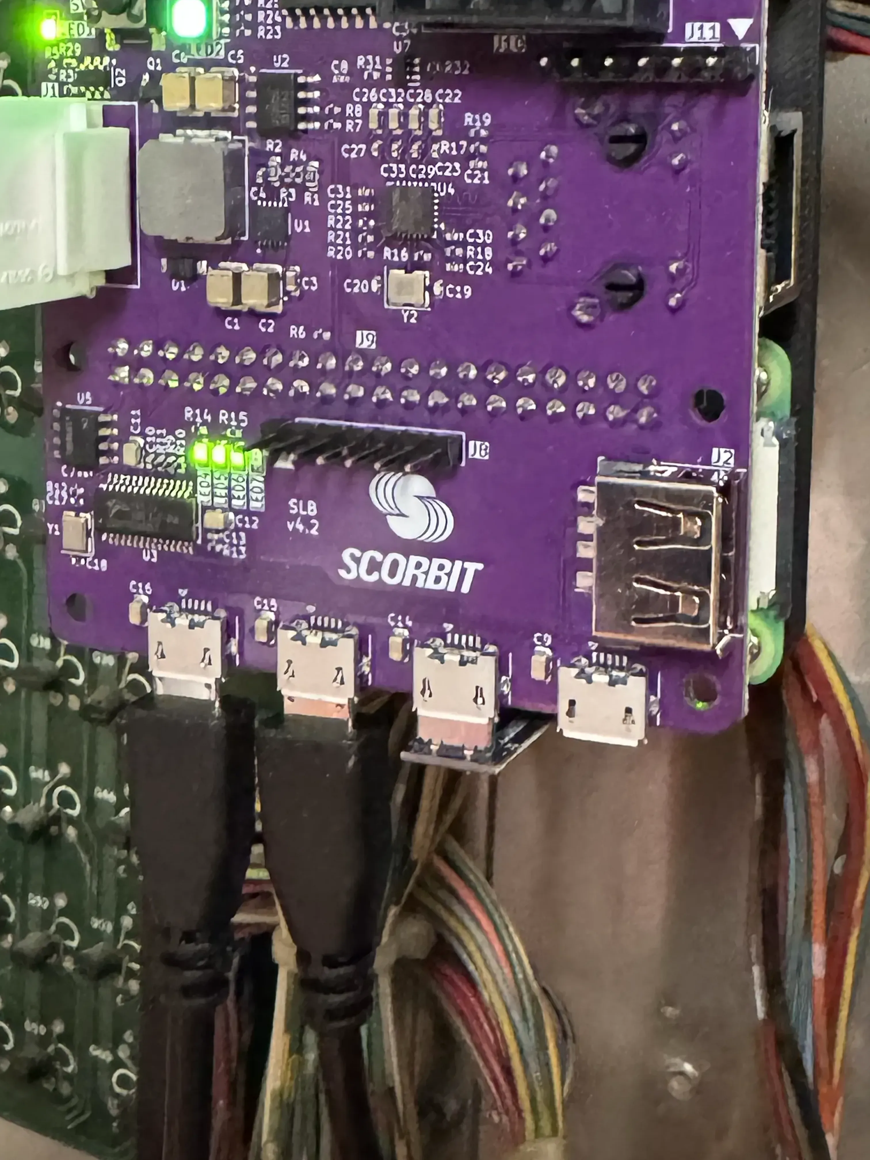
Locate the USB ports on your [machine_type_short] MPU board. Note that one of these ports should be used for the WiFi dongle to provide connectivity to the machine. If your game does not have a WiFi dongle, you must include one in order for the game to connect to the Internet. All new Spike 2 games come with one included. A list of compatible chipsets can be found on the Stern Insider Connected Pinside thread located here.
Insert the provided 3M micro usb to USB A cable into one of the [machine_type_short]'s MPU USB ports.
Insert one end of the 3 meter micro usb cable into the one of the Scorbitron's three ports.
Put the other end of the 3 meter cable through the bottom of the [machine_type_short] backbox, using existing cable management.
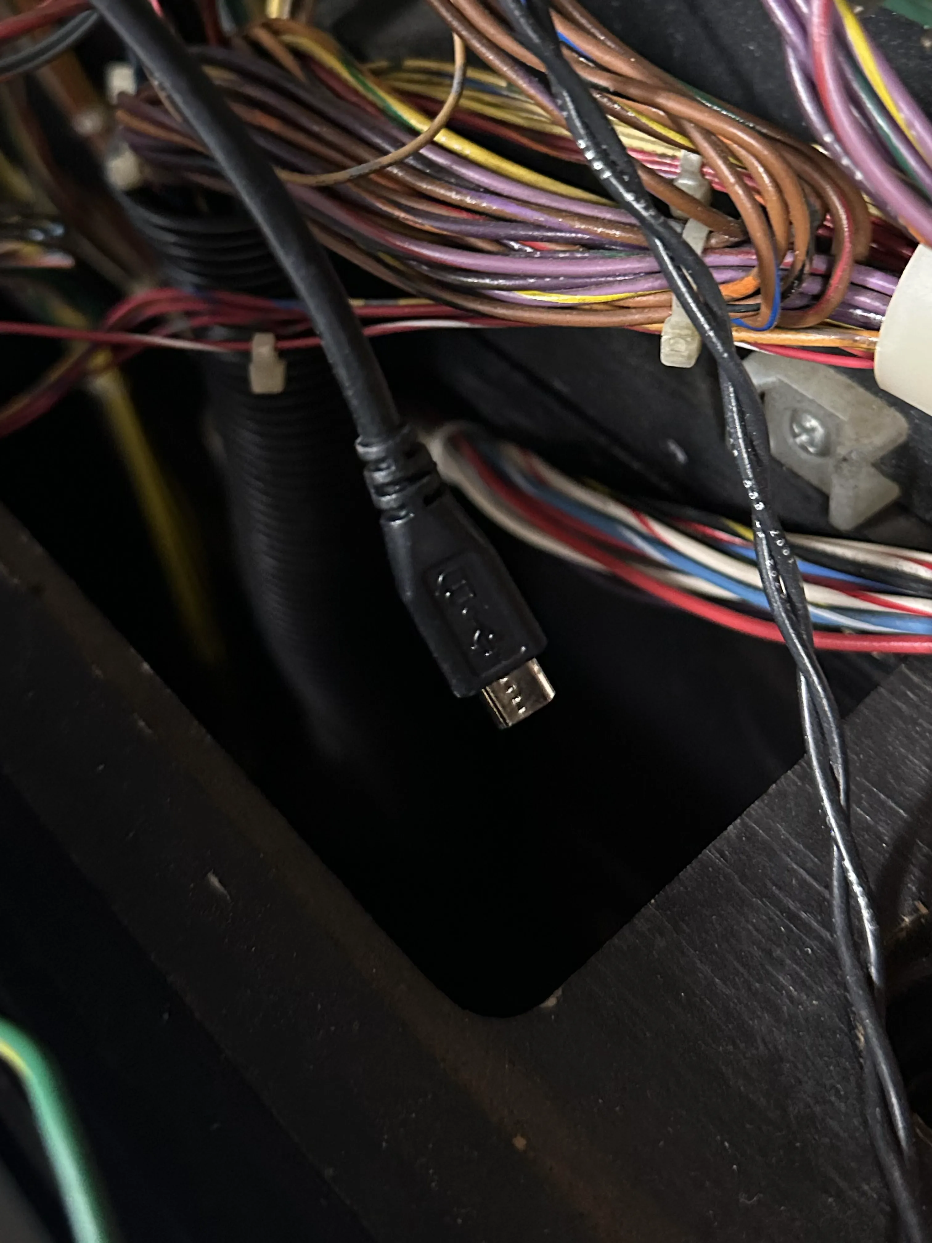
Ensure the cable has enough slack so that if the backbox is folded down there is cable relief and nothing is pulled tight.
Run Cable Along Bottom of Playfield
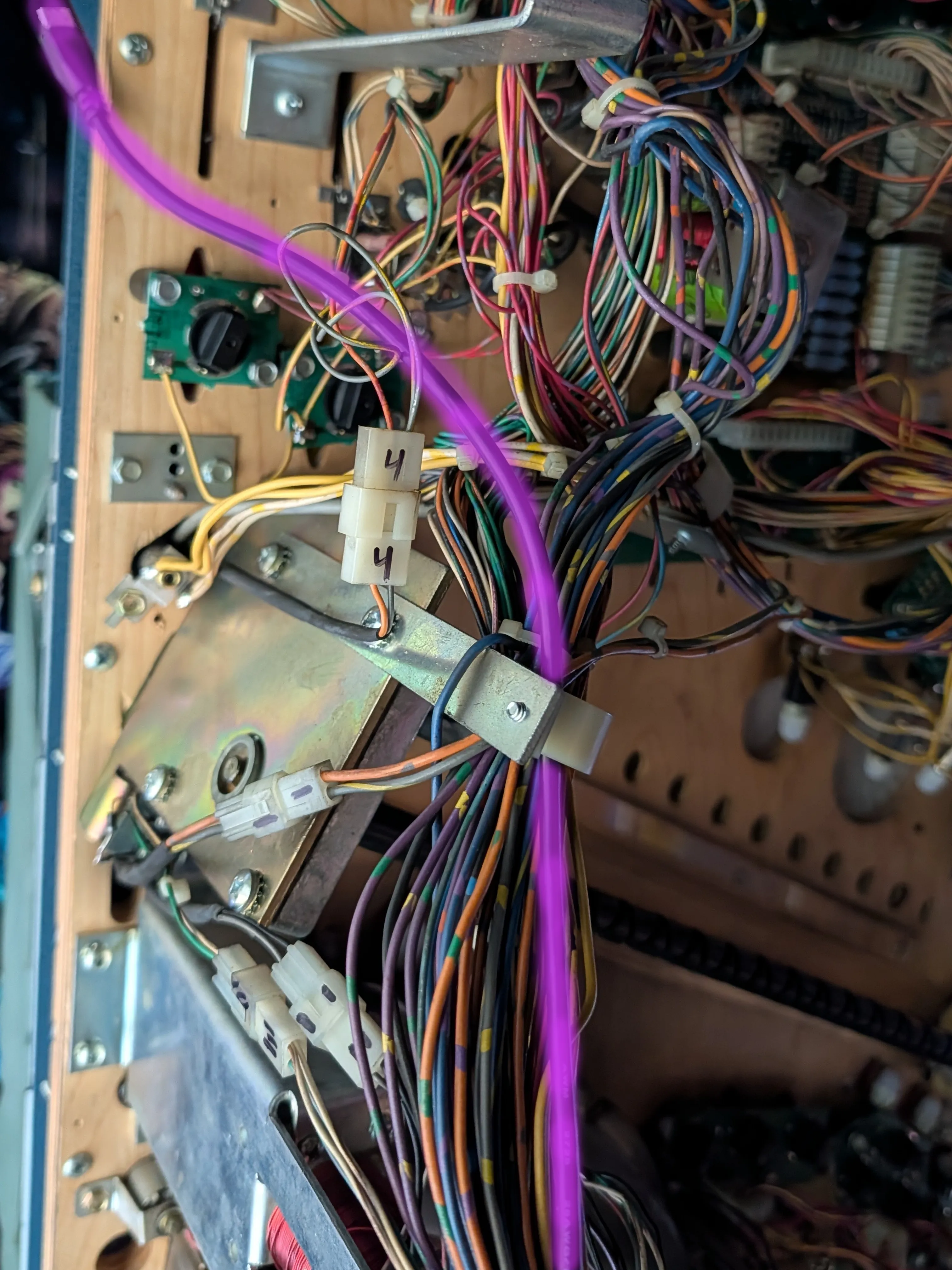
Remove the balls from the playfield and lift it up, either on a stand or against the backbox. Run the 3 meter micro USB cable along the bottom of the playfield using existing cable management, or tie the cable using velcro or cable ties. Avoid any solenoids or other mechanical parts that might catch onto the cable!
Affix Flex Connector and Attach USB Cable
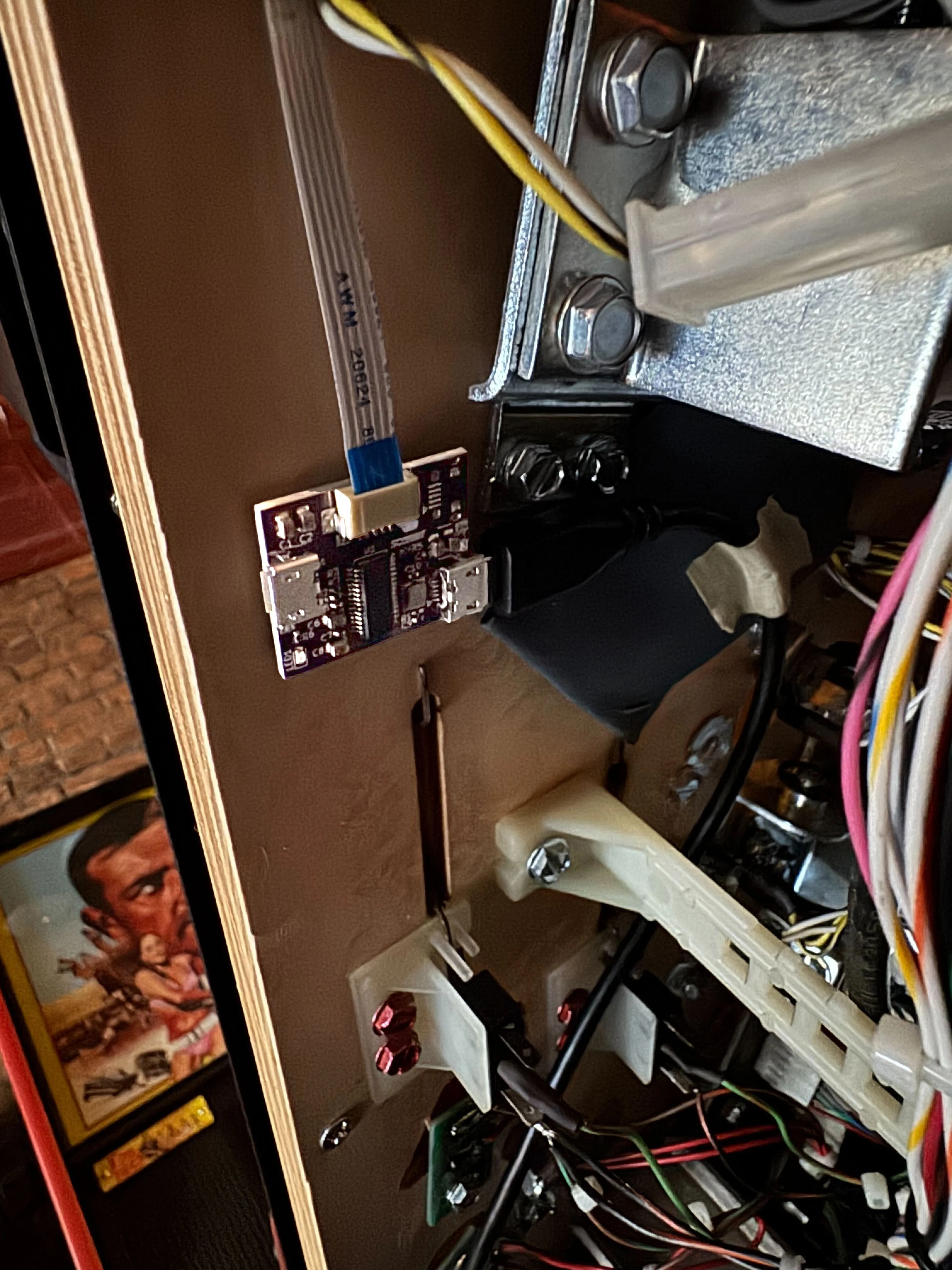
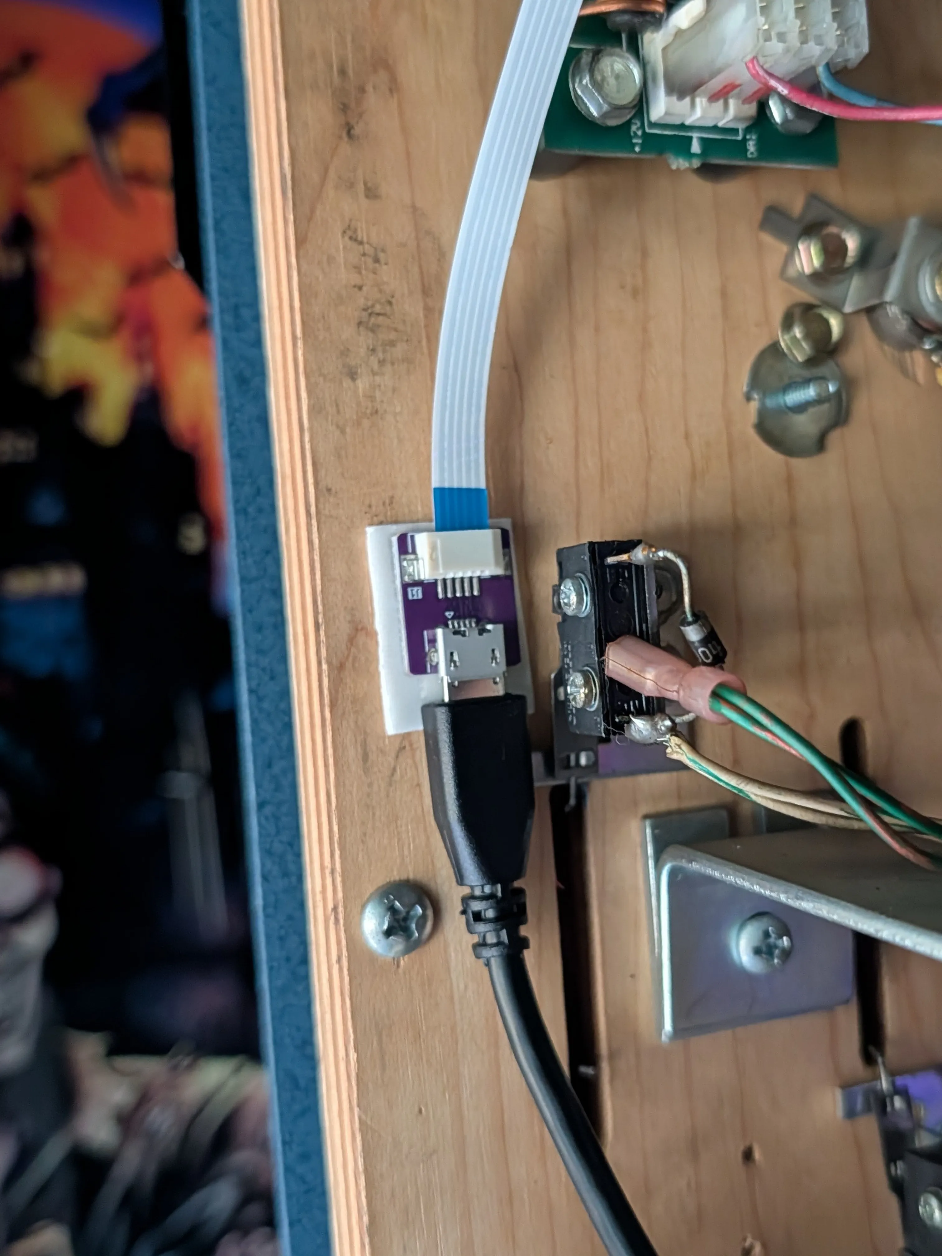
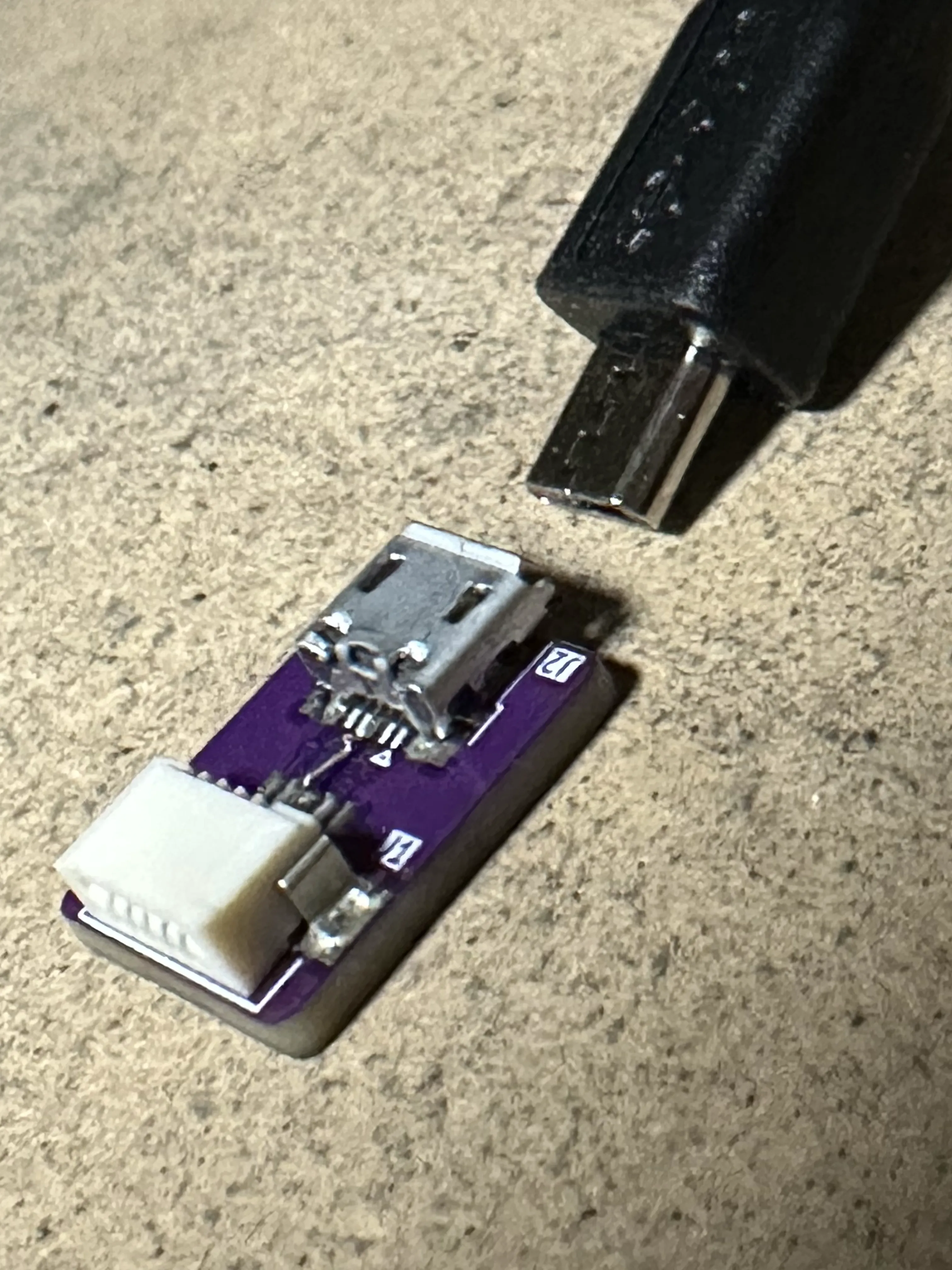
Attach the flex connector to the bottom of the playfield as shown, using two-sided tape. Connect the long usb cable to the flex connector. Remember that the flex connector must be located on the bottom of the playfield so that if the playfield is lifted, it won't break the cable.
Flex Connector Ports
If you look at the back of the connector, you can see the ports that correspond to NFC, MPU, Probe 1 and Probe 2. Note that the USB cable should be plugged into the port labeled MPU. The flex connector is attached later where it is labeled NFC.


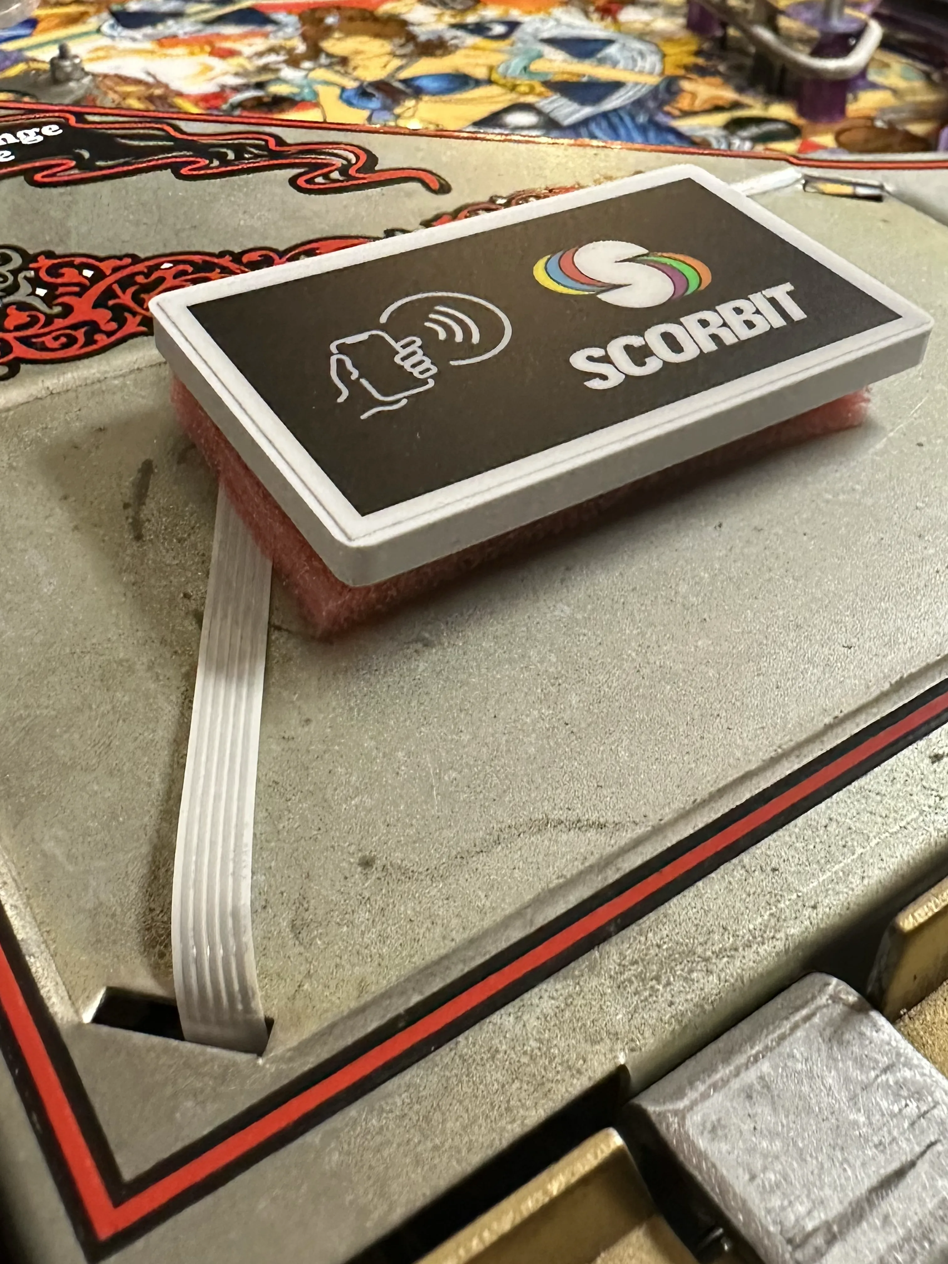
Identify the Scorbit Tap Pad Location
Identify a location above the playfield apron and beneath the glass. We recommend placing the the tap pad over the apron near the instruction card just beneath the surface of the glass, with as much space between the tap pad and glass as possible. Depending on your use of the instruction card, you can move this further back or forward depending on how you feel it best works on the game.

Attach Flex Cable to Tap Pad
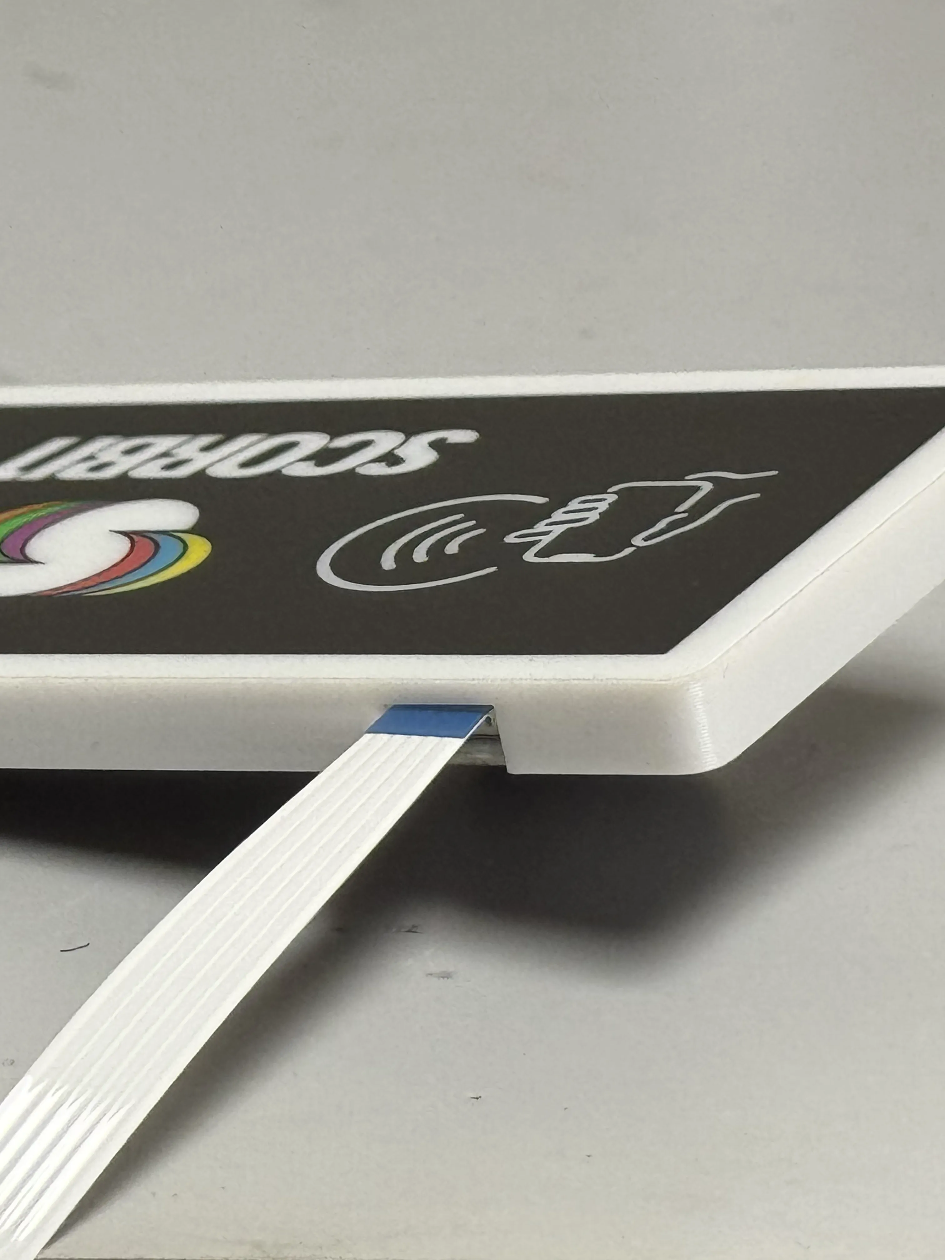
Insert the flex cable into the tap pad, with the exposed metal fingers facing down.
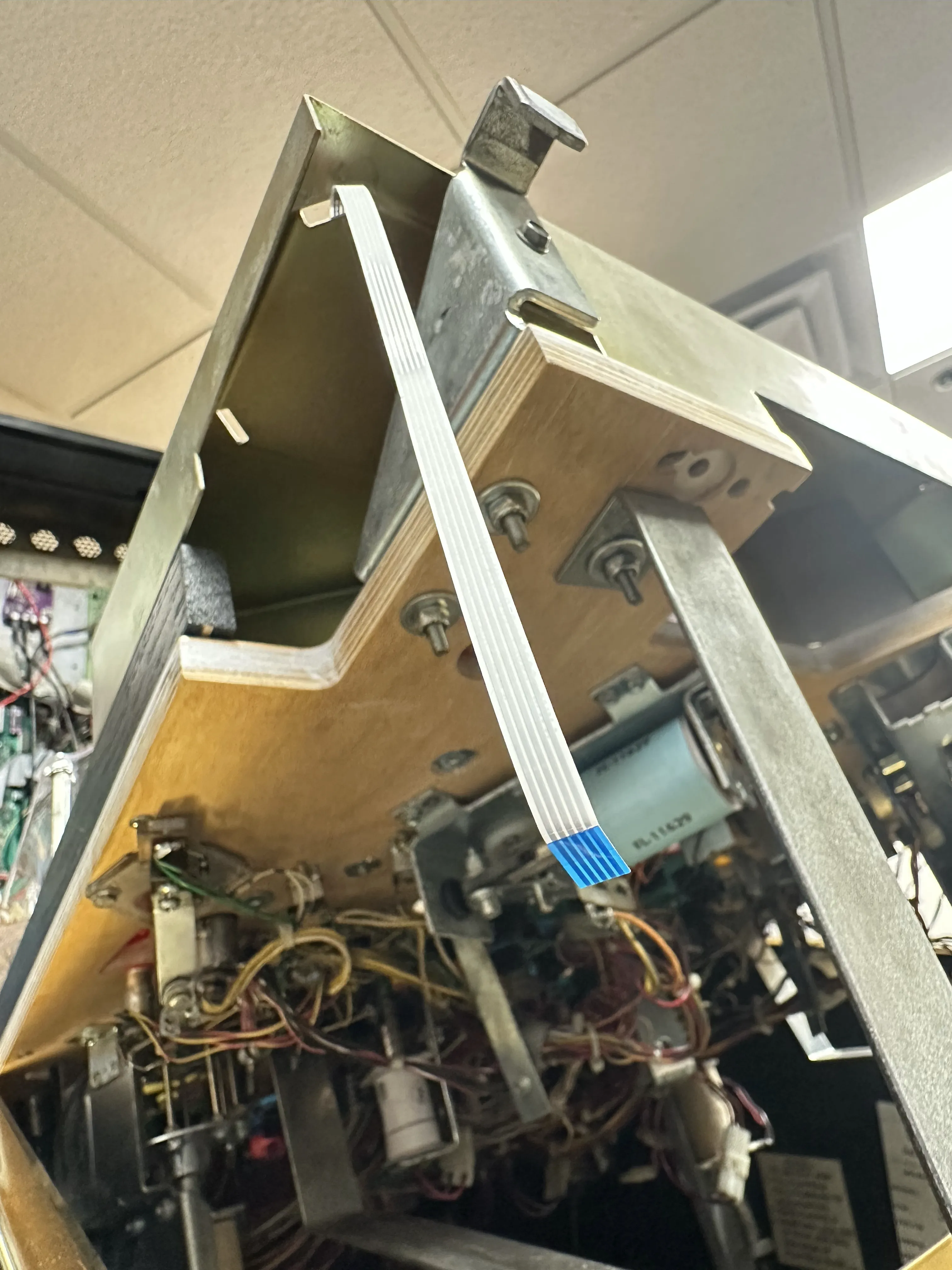
Run Flex Cable Through Apron
Run the flex cable through the instruction card slot hole or through any appropriate path from the apron to under the playfield. The flex cable can be folded to accommodate. Do not fold the flex cable in any one location more than once, as it will damage the cable. In practice, we have found that some black electrical tape can help reduce movement for the white flex cable as it exits the tap pad and through the apron.
Stablize the Tap Pad
After the flex cable is oriented and folded the way you wish, lock the tap pad into place at the desired height. If desired, you may use the provided cradle which snaps into the tap pad and can be adjusted for height breaking off the tabs inside the cradle. You can also affix the pad without a cradle using double sided tape, just be sure to use the location of the glass channel as a guide to how high you place it. Ensure the playfield glass can be inserted and removed one time before finalizing the location.
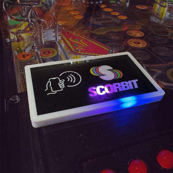
Tap Pad Sensitivity and Height
The perfect location of the tap pad is barely touching the bottom of the glass. Some glasses have coatings that may interfere with the NFC (Near Field Communication) between a smartphone and the pad, so removing distance between the phone and the pad is important. Also, metal aprons, particularly aprons from the late 70's and early 80's, can scramble the NFC signal when they are near the back of the pad. For this reason, we recommend putting the optional cradle or a stacked foam spacer to lift the pad as close to the glass as possible.
Attach Flex Cable to Flex Connector
Now insert the flex cable into the flex connector, with the blue tap facing up and the exposed metal fingers facing the board as shown.